Sure, I would try cleaning up the board using some solvent before doing anything more drastic.
--mark
First post and first hiwatt..
Moderator: Mods
Re: First post and first hiwatt..
The late Hylight DR103 i used to own had the same PCB's-- it also had some of the same heat/smoke damage (but not as severe) on the poweramp PCB----- pics are after my repairs:
Re: First post and first hiwatt..
Gldtp99 Do you know what happened with yours i`ve tried to track down previus owner to find out what burned when and what they have done to it and if you know it might be a clue for me, since ours look simillar.
Re: First post and first hiwatt..
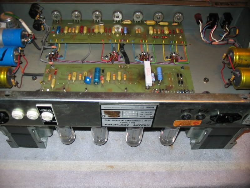
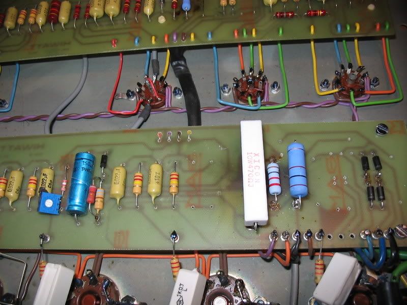
This will happen on the power supply PCB (closest to the output tubes) when there's a catastrophic output tube failure, and the person using the amp doesn't notice right away. I also suspect whomever put a way too large value of fuse in the HT location. ("Darn, the fuse blew. All i have is this 25 amp auto fuse, guess I'll try that.")  The big white resistor has been replaced, the original likely burned to a cinder. I've seen a few of these.
The other PCB, on the other hand, never has large currents flowing through any of it's components, and I am at a loss to explain what happened on that side.
--mark
The other PCB, on the other hand, never has large currents flowing through any of it's components, and I am at a loss to explain what happened on that side.
--mark
Re: First post and first hiwatt..New Question
Thanks Mark, for clarifying it for me. One more question is the cement power resistor supposed to get hot? The amp has allways smelled and runned quite hot and yesterday i went to get to the bottom of it, and accendently burnet myself on that one the powertubes seems fine no one is drasticlly drawing more power so it got me confused..
Re: First post and first hiwatt..
Yes, the big 470 will get *hot* during normal playing, because the screen currents for all four output tubes go through that one resistor.
--mark
--mark
Re: First post and first hiwatt..
Thanks mark you quys here are the best.. i've should have figured that it was the screen resistor, but i'm a completely beginner regarding amps.
Re: First post and first hiwatt..
Hello. I´m here again and freeloathing on your experience..
I Have done a recap joob and wow what a difference it made..
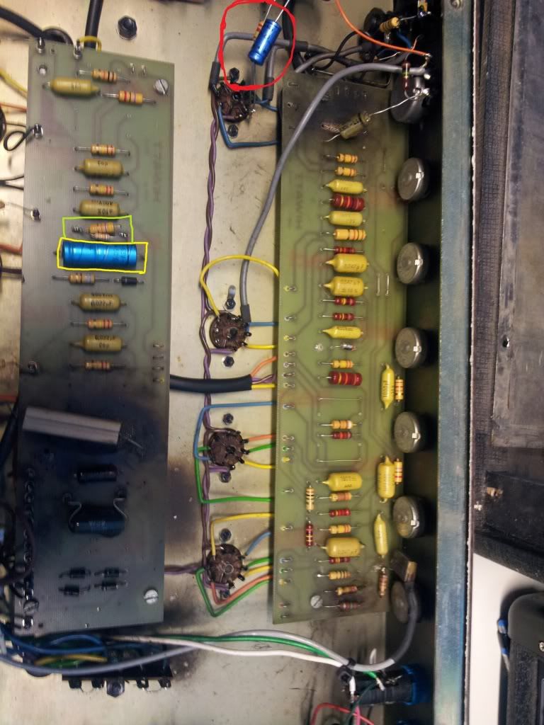
But i got a bit confused with the 100uf/100v bias cap since the two axial i suspect is the one, the values are a bit off on both. The red circled is 100uf/40v and the yellow 150uf/65v. I think it`s the yellow marked but i can be wrong?!
And as i watched this picture i saw the green marked that the replaced the original 4,7k ohm with a 8,4k ohm resistor if i read them correct? Is that something in someway impact the tone?
http://i1165.photobucket.com/albums/q58 ... hiwatt.jpg
Cheers/ Kristofer
I Have done a recap joob and wow what a difference it made..
But i got a bit confused with the 100uf/100v bias cap since the two axial i suspect is the one, the values are a bit off on both. The red circled is 100uf/40v and the yellow 150uf/65v. I think it`s the yellow marked but i can be wrong?!
And as i watched this picture i saw the green marked that the replaced the original 4,7k ohm with a 8,4k ohm resistor if i read them correct? Is that something in someway impact the tone?
http://i1165.photobucket.com/albums/q58 ... hiwatt.jpg
Cheers/ Kristofer
Re: First post and first hiwatt..
The bias cap look original, and that value is not critical. The resistor was likely changed to raise the bias voltage, a worthwhile update given modern tubes.
Unfortunately,I can't quite make out the connections near the red circled components, but the cap is not the original value.
--mark
Unfortunately,I can't quite make out the connections near the red circled components, but the cap is not the original value.
--mark
-
Dr.HI-TONE
- Site Admin
- Posts: 2675
- Joined: Wed Nov 14, 2007 8:51 pm
- Location: HIWATT Valley
Re: First post and first hiwatt..
the red circle appears to be the 100uf cap from T1 or T2 depending on the vintage....going to the ground lug on the 16+32 cap. the resistor which would have originally been a 1.5k is also going to the cap. I can't quite make out the value of it from the photo.
These look to have been scabbed in "point to point" due to the damage of the board.
The original 100uf cap would have been a 16v. version but I suspect it exploded causing the damage.
These look to have been scabbed in "point to point" due to the damage of the board.
The original 100uf cap would have been a 16v. version but I suspect it exploded causing the damage.
Re: First post and first hiwatt..
Correct good dr. It´s from negative on the 16/32uf to p1 and the resistor is 1,5k. So i would change that one back to a 100uf 16v for original spec correct? And as i suspected the 150uf cap is the bias cap correct? just to clarifiye? Because i`m terrible bad att reading schematics but i try to learn, so this i s a really good learning by doing experience, thanks!
And thanks for pointing out the bias resistor, so now i know where to put a pot so my old mullards won`t run that hot.
And thanks for pointing out the bias resistor, so now i know where to put a pot so my old mullards won`t run that hot.
-
Dr.HI-TONE
- Site Admin
- Posts: 2675
- Joined: Wed Nov 14, 2007 8:51 pm
- Location: HIWATT Valley
Re: First post and first hiwatt..
you could leave the 100uf/40v. cap alone. It is the same value as the 16v. variety, but capable of handling more voltage. It should have little to no effect on the tone based on a higher rating.
yes, the 150uf is the bias cap.
yes, the 150uf is the bias cap.
Re: First post and first hiwatt..
Thanks for clarifycation on everything.
Cheers/K
Cheers/K
-
Dr.HI-TONE
- Site Admin
- Posts: 2675
- Joined: Wed Nov 14, 2007 8:51 pm
- Location: HIWATT Valley
Re: First post and first hiwatt..
you are welcome!
Re: First post and first hiwatt..
HAHA more questions ahead,soon it will end i hope..
This cap if i read the schematics right it should be a 0,022uf(22nf) cap right? and not a 0,033uf cap that who ever "repaired" this put in, i goes from pin6 to normal volume if i`m not mistaken( first mustard cap from left on preamp section on gldtp99`s picture.
And if i change it back it would make normal sound a bit brighter right?
- 20120411_145940.png (487.33 KiB) Viewed 3059 times