Page 3 of 3
Re: DR201
Posted: Fri Jul 19, 2013 8:30 pm
by Dad3353
nightterrors wrote:about the Y cable....
I have an amp splitter in a 1950a pedal enclosure and theres one input, 2 outputs. Before I had an amp selector I used it to run two amps... could this work to hook up the DR201 to two four ohm cabs? I doubt it, just trying to think of things I have to use.
Good evening, nightterrors (or may I call you night..?)...
Definitely not, without completely rewiring the box. The amp splitter runs the 2 signals in parallel; using it 'as is' for running cabs would run them in parallel, too. The two 4 ohm cabs would therefore present a 2 ohm load to the amp, and could cause damage.
If, however, the internal wiring was modified so as to have the 2 outputs in series, it would do the job. The wiring would have to be 'beefy' enough (none of this flimsy shielded signal cable; real speaker wiring is needed..).
Running cabs in series can be, and is, done, but has pitfalls which would have to be balanced with the advantages. Any single failure in the cabling, anywhere in the chain, results in running the amp without a load. If you've never experienced this, be assured that you do not want to start. Amp 'destruction' is often the almost instant result, if you're on stage playing hard. Pretty short-lived pyrotechnics (smoke, flames...), and darned expensive. Series cabs..? As an experiment, fine. To try it out briefly, why not..? As a regular working rig, I wouldn't do it. YMMV, of course.
Re: DR201
Posted: Fri Jul 19, 2013 8:35 pm
by nightterrors
Yeah, I figured!
Thanks man. I will ask around and get someone to re-wire it for me.
Re: DR201
Posted: Sat Jul 20, 2013 3:12 pm
by nightterrors
Re: DR201
Posted: Mon Jul 22, 2013 5:57 pm
by OldSchoolDave
Back on-line after a marathon move. If I EVER talk about moving again, somebody, please slap me upside the head with a 2x4

!
The switches are not original. You might find a Marshall guy who'll pay you for the complete one. Good to see the fans were just screwed to the mesh. Too many cases have been unnecessarily cut. You don't need 'em - get rid of 'em.
As for the stuck/stripped bolt, try leveraging a flat head screw driver between the chassis and the case. Keeping upward pressure on that might help the bolt back out.
...more unpacking to do

...
Dave
Re: DR201
Posted: Tue Jul 23, 2013 9:45 pm
by Stu_R
nightterrors wrote: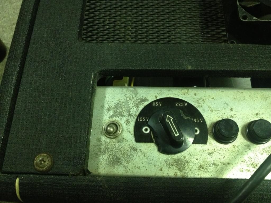
Any clue what the extra switch to the left does?
My 200 just has a rubber cap there to seal the hole, I always assumed it was for a Canadian hard-wire fix.
Re: DR201
Posted: Tue Jul 23, 2013 10:17 pm
by Dr.HI-TONE
They would have had the rubber cap originally.
that switch is a later add on.
Re: DR201
Posted: Wed Jul 24, 2013 3:19 am
by OldSchoolDave
Stu_R wrote:
Any clue what the extra switch to the left does?
nightterrors wrote:
In the 70's he also added 2 fans to the back mesh/cage that can come off, not screwed into the head case or anything, but he added a switch for it on the back of the chassis.
Re: DR201
Posted: Wed Jul 24, 2013 9:42 am
by Stu_R
OldSchoolDave wrote:Stu_R wrote:
Any clue what the extra switch to the left does?
nightterrors wrote:
In the 70's he also added 2 fans to the back mesh/cage that can come off, not screwed into the head case or anything, but he added a switch for it on the back of the chassis.
Ahaa! I just had a thought that it looked like a mains switch should do, so maybe a front switch was moved to there & the new switches installed to make a matching pair?
I've seen 400s with fans retro-fitted but never seen anyone who thought a 200 might need them.
Re: DR201
Posted: Tue Jan 14, 2014 8:22 pm
by teethdream
OldSchoolDave wrote:nightterrors wrote:
Hmm.... well.. would you do it? haha.
NO! Hook up the cabs in series and set the amp to 8 ohms.
Dave
EDIT: Here's a down and dirty sketch of a Series Y harness. You could substitute Male plugs for the Female jacks. Just make sure everything is plugged in before firing up the amp.
Series Y-Cable by OSD - 640px.jpg
Sorry to bump an older thread, but this diagram has got the wheels in my head turning right now.
I'm thinking maybe Ill make this in a box form (maybe using a guitar pedal box?), only instead using 3 speakon jacks instead of quarter inch jacks. This would make things a little safer (ie: someone wouldn't be able to trip over a cable and accidentally unplug it from the box or have it vibrate loose creating an open circuit). Modern Ampeg 810s (the most common backline bass cab in my experiences) have speakon jacks as well, so the only part that wouldn't be "locked" in place is the connection to the amp. This box could be very useful, as most times I show up at a venue there already is an Ampeg 810 provided for backline and as I bring my own it's sometimes nice to be able to use two. That's one thing I do miss about having a SVT as my main touring rig, the ability to hit 2ohms safely. I will post my results when I finish. Thanks for the diagram OSD!
Re: DR201
Posted: Tue Jan 14, 2014 10:26 pm
by OldSchoolDave
teethdream wrote:
Sorry to bump an older thread, but this diagram has got the wheels in my head turning right now.
I like your variation on the theme!
I'd use a simple rectangular "kit" box. Hardest part would be cutting the holes for the speakon jacks. Or, if size weren't a limiting factor, mounting ready-made speakon jack plates into a light duty plywood (or pine...for the purists

) box would do the trick.
teethdream wrote:I will post my results when I finish.
Please do!
Dave


