How to Install Adjustable Bias on Hylight Era DR103
Posted: Sat Sep 03, 2011 3:46 pm
I recently acquired a '73 DR103. Upon doing the usual preliminary checks, I recorded plate and screen voltages in the 475V range, with a set of new power tubes drawing ~60ma at idle. Obviously, drawing 28W from the power tubes at idle is not a recipe for longevity and reliability (as many have discovered).
The problem with the DR103 is no bias adjustment exists, but this is easily remedied with a single inexpensive bias pot. The install takes about 10 min, and does not require making changes to the original wiring, which is nice if one aims to preserve the integrity of an amp in good original condition.
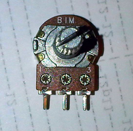
The only component required is a 1/2 watt linear trim pot that measures 1-2 Meg, and is configured for PC board mount. These can be had on Ebay if you can't find one from your favorite parts supplier. Note that the pot must measure at least 1 Meg to gain the full range of adjustment. The tiny 25k pots that work with Marshalls are useless here.
The pot should look like this:

Looking at the pot as it is shown in the photo, take the right pin, bend it inward toward the center pin, and solder those two together.
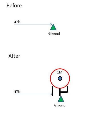
The next thing is to locate the 47k resistor (yellow/violet/orange) in the bias circuit, which is adjacent to the 100uF electrolytic cap on the terminal strip nearest to the power tubes. One end of that 47k shares a connection with the (-) side of the 100uF bias filter cap. The other end of the 47k is soldered to a terminal on the strip that serves as a grounding point. It is the grounded end that we want. Lift the end of the resistor from the grounded terminal.
What we do now is carefully solder the formerly grounded end of the 47k resistor to the left terminal of the pot. If the left terminal also has a small circular eyelet as does the pot shown in the photo, it is easier to simply insert the resistor lead into that small eyelet and solder it.
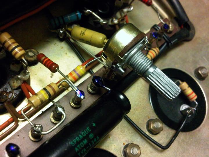
Finally, we heat the grounded terminal on the strip with the soldering iron, and carefully insert the center pin of the pot into that grounded terminal. When the connection cools, the pot should be firmly anchored into that grounded terminal.
What this does is give us the ability to increase the resistance between the bias voltage feed and ground, which allows almost the full negative bias voltage to be applied to the power tubes. Whereas the bias voltage was previously fixed at -38V, it can now be adjusted to around -45V if required, which represents almost the full voltage available from the bias tap.
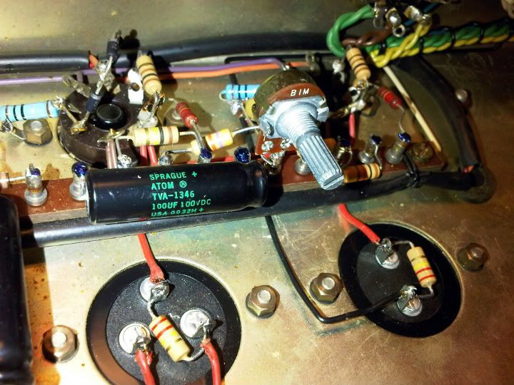
The end result should look like this:


This gives the ability to decrease idle current by ~20ma at idle, which provides ample bias range without having to redesign the circuit or perform major surgery.
WARNING: There are high voltages present very close to this pot, so extreme care should be exercised when making a bias adjustment. DO NOT allow your hand to touch anything other than the pot!
The problem with the DR103 is no bias adjustment exists, but this is easily remedied with a single inexpensive bias pot. The install takes about 10 min, and does not require making changes to the original wiring, which is nice if one aims to preserve the integrity of an amp in good original condition.
The only component required is a 1/2 watt linear trim pot that measures 1-2 Meg, and is configured for PC board mount. These can be had on Ebay if you can't find one from your favorite parts supplier. Note that the pot must measure at least 1 Meg to gain the full range of adjustment. The tiny 25k pots that work with Marshalls are useless here.
The pot should look like this:

Looking at the pot as it is shown in the photo, take the right pin, bend it inward toward the center pin, and solder those two together.
The next thing is to locate the 47k resistor (yellow/violet/orange) in the bias circuit, which is adjacent to the 100uF electrolytic cap on the terminal strip nearest to the power tubes. One end of that 47k shares a connection with the (-) side of the 100uF bias filter cap. The other end of the 47k is soldered to a terminal on the strip that serves as a grounding point. It is the grounded end that we want. Lift the end of the resistor from the grounded terminal.
What we do now is carefully solder the formerly grounded end of the 47k resistor to the left terminal of the pot. If the left terminal also has a small circular eyelet as does the pot shown in the photo, it is easier to simply insert the resistor lead into that small eyelet and solder it.
Finally, we heat the grounded terminal on the strip with the soldering iron, and carefully insert the center pin of the pot into that grounded terminal. When the connection cools, the pot should be firmly anchored into that grounded terminal.
What this does is give us the ability to increase the resistance between the bias voltage feed and ground, which allows almost the full negative bias voltage to be applied to the power tubes. Whereas the bias voltage was previously fixed at -38V, it can now be adjusted to around -45V if required, which represents almost the full voltage available from the bias tap.
The end result should look like this:


This gives the ability to decrease idle current by ~20ma at idle, which provides ample bias range without having to redesign the circuit or perform major surgery.
WARNING: There are high voltages present very close to this pot, so extreme care should be exercised when making a bias adjustment. DO NOT allow your hand to touch anything other than the pot!