How to Install Adjustable Bias on Hylight Era DR103

HIWATT amps from the Hylight Electronics era

Moderator: Mods

Ted B
Posts: 35
Joined: Thu Jun 30, 2011 10:38 pm
Location: Birmingham, AL - New Orleans, LA

How to Install Adjustable Bias on Hylight Era DR103

Post by Ted B »

I recently acquired a '73 DR103. Upon doing the usual preliminary checks, I recorded plate and screen voltages in the 475V range, with a set of new power tubes drawing ~60ma at idle. Obviously, drawing 28W from the power tubes at idle is not a recipe for longevity and reliability (as many have discovered).

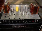
The problem with the DR103 is no bias adjustment exists, but this is easily remedied with a single inexpensive bias pot. The install takes about 10 min, and does not require making changes to the original wiring, which is nice if one aims to preserve the integrity of an amp in good original condition.

The only component required is a 1/2 watt linear trim pot that measures 1-2 Meg, and is configured for PC board mount. These can be had on Ebay if you can't find one from your favorite parts supplier. Note that the pot must measure at least 1 Meg to gain the full range of adjustment. The tiny 25k pots that work with Marshalls are useless here.

The pot should look like this:

Image

Looking at the pot as it is shown in the photo, take the right pin, bend it inward toward the center pin, and solder those two together.

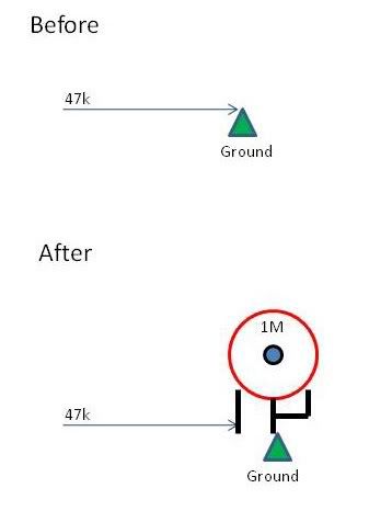
The next thing is to locate the 47k resistor (yellow/violet/orange) in the bias circuit, which is adjacent to the 100uF electrolytic cap on the terminal strip nearest to the power tubes. One end of that 47k shares a connection with the (-) side of the 100uF bias filter cap. The other end of the 47k is soldered to a terminal on the strip that serves as a grounding point. It is the grounded end that we want. Lift the end of the resistor from the grounded terminal.

What we do now is carefully solder the formerly grounded end of the 47k resistor to the left terminal of the pot. If the left terminal also has a small circular eyelet as does the pot shown in the photo, it is easier to simply insert the resistor lead into that small eyelet and solder it.

Finally, we heat the grounded terminal on the strip with the soldering iron, and carefully insert the center pin of the pot into that grounded terminal. When the connection cools, the pot should be firmly anchored into that grounded terminal.

What this does is give us the ability to increase the resistance between the bias voltage feed and ground, which allows almost the full negative bias voltage to be applied to the power tubes. Whereas the bias voltage was previously fixed at -38V, it can now be adjusted to around -45V if required, which represents almost the full voltage available from the bias tap.

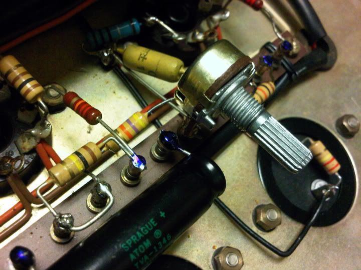
The end result should look like this:

Image

Image

Image

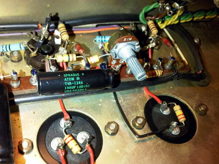
This gives the ability to decrease idle current by ~20ma at idle, which provides ample bias range without having to redesign the circuit or perform major surgery.

WARNING: There are high voltages present very close to this pot, so extreme care should be exercised when making a bias adjustment. DO NOT allow your hand to touch anything other than the pot!
User avatar
Dr.HI-TONE
Site Admin
Posts: 2673
Joined: Wed Nov 14, 2007 8:51 pm
Location: HIWATT Valley

Re: How to Install Adjustable Bias on Hylight Era DR103

Post by Dr.HI-TONE »

Hmmmm.....I may have to try this.
I am a stickler about not modding my vintage pieces, but this is minor enough that the benefit should outweigh any negatives
http://www.HI-TONE-Amps.com

HI-TONE, when only the best will do.

DR-F
Ted B
Posts: 35
Joined: Thu Jun 30, 2011 10:38 pm
Location: Birmingham, AL - New Orleans, LA

Re: How to Install Adjustable Bias on Hylight Era DR103

Post by Ted B »

That's my sentiment as well, and I went into this bearing that in mind. Like I said, it only requires lifting one leg of a resistor, nothing else. Nothing removed, replaced, cut, clipped, or otherwise.

Just remove the pot, re-solder that single resistor lead back to the ground terminal, and you're right back to square one without evidence of anything having been done.

But equally importantly, this minor mod works.
User avatar
Dr.HI-TONE
Site Admin
Posts: 2673
Joined: Wed Nov 14, 2007 8:51 pm
Location: HIWATT Valley

Re: How to Install Adjustable Bias on Hylight Era DR103

Post by Dr.HI-TONE »

maybe most importantly: "it works"

8)
http://www.HI-TONE-Amps.com

HI-TONE, when only the best will do.

DR-F
marwatt
Posts: 27
Joined: Tue Nov 20, 2007 3:07 pm
Location: Italy

Re: How to Install Adjustable Bias on Hylight Era DR103

Post by marwatt »

is really important to have a 1/2W pot??
How much current run through tha pot?

thanx marwatt
ciao Marwatt
riba2233
Posts: 168
Joined: Sat Oct 02, 2010 12:55 pm
Location: Croatia

Re: How to Install Adjustable Bias on Hylight Era DR103

Post by riba2233 »

marwatt wrote:is really important to have a 1/2W pot??
How much current run through tha pot?

thanx marwatt
Don't worry, that's not a 1/2w pot. You can use any.


@Ted B: could you please explain the diodes?
Ted B
Posts: 35
Joined: Thu Jun 30, 2011 10:38 pm
Location: Birmingham, AL - New Orleans, LA

Re: How to Install Adjustable Bias on Hylight Era DR103

Post by Ted B »

Those diodes were installed before I acquired the amp, but they serve as a means of protecting the output transformer. Here is a brief explanation:

http://books.google.com/books?id=bmeE_H ... &q&f=false
Pinus
Posts: 29
Joined: Wed Jan 11, 2012 7:57 am

Re: How to Install Adjustable Bias on Hylight Era DR103

Post by Pinus »

TedB plesase with 1M linear pot whats the range of the Grid Voltage that you can set? It run linear from -38 to -45 or almost to -45 at starting rotate the pot? Thank you, Daniele
Ted B
Posts: 35
Joined: Thu Jun 30, 2011 10:38 pm
Location: Birmingham, AL - New Orleans, LA

Re: How to Install Adjustable Bias on Hylight Era DR103

Post by Ted B »

If I remember correctly, the maximum bias voltage is around -34-35V, which is almost all the transformer delivers. I do not remember the opposite end of the range, but it is unimportant.
Pinus
Posts: 29
Joined: Wed Jan 11, 2012 7:57 am

Re: How to Install Adjustable Bias on Hylight Era DR103

Post by Pinus »

Thank you
fusionid
Posts: 7
Joined: Thu Feb 09, 2012 10:23 pm

Re: How to Install Adjustable Bias on Hylight Era DR103

Post by fusionid »

Can this mod be used for the DR503??

I see in the schematics it is a 27k as opposed to a 47k
Ted B
Posts: 35
Joined: Thu Jun 30, 2011 10:38 pm
Location: Birmingham, AL - New Orleans, LA

Re: How to Install Adjustable Bias on Hylight Era DR103

Post by Ted B »

Yes, it should work just the same.
User avatar
mhuss
Site Admin
Posts: 1439
Joined: Thu Nov 15, 2007 5:40 am

Re: How to Install Adjustable Bias on Hylight Era DR103

Post by mhuss »

Not exactly the same. Recall the 504 uses a Marshall style large value resistor going to the B+ secondary, versus the separate bias winding on the 103. I would recommend lifting the non-grounded end of the 27k and inserting a 20k pot.

--mark
User avatar
MrMojo
Posts: 47
Joined: Tue Nov 16, 2010 5:09 pm
Location: Northern Virginia

Re: How to Install Adjustable Bias on Hylight Era DR103

Post by MrMojo »

I have always found it to be a nice, practical addition, easily reversed.
Hiwatt - can't stop at just one
Hi Matt
Posts: 14
Joined: Wed Apr 11, 2012 10:41 pm

Re: How to Install Adjustable Bias on Hylight Era DR103

Post by Hi Matt »

Hi there,

I acquired a 76 Hiwatt DR103 and need to replace the power tubes that are extremely old. I really can't decide which way I should go.
1. Keep it unmodified and find strong enough tubes
2. Make Ted's mod which seems quite simple and uninvasive
3. Make MHuss bias circuit mod

I'm really not an electronic expert so that's why I ask you guys. Which of these solutions would you choose?
Is Ted's mod as efficient as MHuss Bias circuit mod or is it at least sufficient with current production tubes?

And last question, could you point me out some informative (and understandable) litterature on the procedure I should follow to set the bias.

Thank you in advance.

Matthias
Post Reply