congrats!
the amp is stuck with the 4,8,16 ohm options.
You are "probably" safe running both cabs with the amp set to 4 ohms.
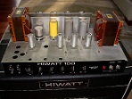
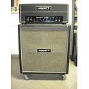
DR201
Moderator: Mods
-
Dr.HI-TONE
- Site Admin
- Posts: 2675
- Joined: Wed Nov 14, 2007 8:51 pm
- Location: HIWATT Valley
-
nightterrors
- Posts: 24
- Joined: Wed Jun 26, 2013 6:12 pm
- Location: Canada
Re: DR201
Thanks!
Hmm.... well.. would you do it? haha.
Hmm.... well.. would you do it? haha.
-
Dr.HI-TONE
- Site Admin
- Posts: 2675
- Joined: Wed Nov 14, 2007 8:51 pm
- Location: HIWATT Valley
Re: DR201
Only if I was in a pinch. I don't like to mismatch impedances.
But hopefully Mark will add his expert opinion.
But hopefully Mark will add his expert opinion.
-
mikhailwatt
- Posts: 858
- Joined: Thu Nov 15, 2007 2:46 am
- Location: Austin TX
Re: DR201
Cranked up, with a bass guitar, seems like that "could" be asking for trouble.Dr.HIWATT wrote:But hopefully Mark will add his expert opinion.
"Paging the Professor........"
You can almost feel the current flowing
You can almost see the circuits blowing
You can almost see the circuits blowing
-
OldSchoolDave
- Posts: 2060
- Joined: Wed Nov 14, 2007 9:24 pm
- Location: HP, NC USA
- Contact:
Re: DR201
NO! Hook up the cabs in series and set the amp to 8 ohms.nightterrors wrote:
Hmm.... well.. would you do it? haha.
Dave
EDIT: Here's a down and dirty sketch of a Series Y harness. You could substitute Male plugs for the Female jacks. Just make sure everything is plugged in before firing up the amp.
- Series Y-Cable by OSD - 640px.jpg (58.73 KiB) Viewed 4441 times
-
Dr.HI-TONE
- Site Admin
- Posts: 2675
- Joined: Wed Nov 14, 2007 8:51 pm
- Location: HIWATT Valley
Re: DR201
Excellent idea Dave!
I can't believe that I didn't think of that, but that is what you highly knowledgeable and experienced gents are here for!

I can't believe that I didn't think of that, but that is what you highly knowledgeable and experienced gents are here for!
-
OldSchoolDave
- Posts: 2060
- Joined: Wed Nov 14, 2007 9:24 pm
- Location: HP, NC USA
- Contact:
Re: DR201
Sounds a lot nicer than OLD FARTSDr.HIWATT wrote:...highly knowledgeable and experienced gents...
my pleasure,
Dave
Re: DR201
The series idea is best. You can either make up a cable as Dave suggested, or duplicate that connection in a small box and use three normal cables. I like the box better, because 'normal' cables are easier to find and replace in a pinch. If you make a box, use standard Cliff/Rean plastic jacks like those on the back of the amp to avoid shorting the sleeve connections together.
--mark
--mark
-
nightterrors
- Posts: 24
- Joined: Wed Jun 26, 2013 6:12 pm
- Location: Canada
Re: DR201
OldSchoolDave wrote:NO! Hook up the cabs in series and set the amp to 8 ohms.nightterrors wrote:
Hmm.... well.. would you do it? haha.
Dave
EDIT: Here's a down and dirty sketch of a Series Y harness. You could substitute Male plugs for the Female jacks. Just make sure everything is plugged in before firing up the amp.
Great! thanks!
So set the amp to 8 ohms, plug this cable into the amp and the two other ends into each cab? (just double checking!)
Where can I get a cable like this that is durable?
Another question... is the DR201 actually rated at 200 watts? or less? I'm talking both the KT88 and El34 models.
-
OldSchoolDave
- Posts: 2060
- Joined: Wed Nov 14, 2007 9:24 pm
- Location: HP, NC USA
- Contact:
Re: DR201
Correct. That particular Y junction will create a Series connections between your two 4 ohm cabs, resulting in an 8 ohm load to the amp. Realize that if one or the other cab is disconnected, there will be an open circuit (no sound, no load, be careful).nightterrors wrote: So set the amp to 8 ohms, plug this cable into the amp and the two other ends into each cab? (just double checking!)
AFAIK, you'll have to make one. I've never seen one commercially available. I do like Mark's idea of a box (with insulated jacks), as it'd be more durable. But, if built correctly, a Y Cable can be plenty stout.nightterrors wrote: Where can I get a cable like this that is durable?
I'll let the good professor answer that. Don't have access to a scope.nightterrors wrote: Another question... is the DR201 actually rated at 200 watts? or less? I'm talking both the KT88 and El34 models.
Dave
Re: DR201
We're in the process of finding that out, and will be measuring some vintage 201s as soon as the Doc has some free time.nightterrors wrote: Another question... is the DR201 actually rated at 200 watts? or less? I'm talking both the KT88 and El34 models.
--mark
Re: DR201
This info might be of use in the meantime . http://www.dst-engineering.com/tech-hiwatt201.htmmhuss wrote:We're in the process of finding that out, and will be measuring some vintage 201s as soon as the Doc has some free time.nightterrors wrote: Another question... is the DR201 actually rated at 200 watts? or less? I'm talking both the KT88 and El34 models.
--mark
Hiwatt Custom 200 (6 x EL34, 1978)
I recently had a Hiwatt Custom 200 come across my bench for a minor tune-up. This included a cap job and upgrade of the screen grid resistors along with the usual pot cleaning, bias check, etc. This particular amp is the 6 x EL34 version with 2 output jacks & 4 inputs (dated 8-28-78,s/n 13059). Usually, when I have an amp on the bench I take a quick set of measurements to confirm everything is as it should be and also as a reference point should future repairs be needed of if a similar unit comes in for work.
A few basic observations of this unit are in order. First off, this is quite the amplifier. It currently belongs to Jeff Swanson (Swansoncabinets.com) and is used with two Mesa Boogie 1 x 15 cabinets (EVM 15B's) for Bass guitar. Jeff had changed the output tubes from some obscure German pieces to Electro-Harmonix. He wanted me to make sure the amp was biased properly and was also curious to know where it operated. Sound wise this thing is an absolute monster. I can say this from a practical standpoint as I played lead guitar in a band with Jeff for quite sometime. The biggest concern though is the tremendous amount of heat generated. Just doing a little quick math shows that each output tube is dissipating about 19.4 watts of idle plate power, 10 watts of filament heat and about 1.5 watts of screen grid for a total of nearly 31 watts. Multiply that by 6 tubes and you have 186 watts of heat. Think about a couple of 100-watt light bulbs in a cabinet this size and you will immediately have an idea of the heat build up. However, this is still well within the limits of the EL34EH tubes and given the fact that they are mounted close to the vented rear panel, the heat doesn't appear to be a problem.
The most noticeable aspect of this build are the 2 HUGE transformers. The only complaint I have with these guys is that gravity and my age work against each other when it comes to getting the amp out of it's enclosure. However, these transformers are very solid performers. Respectable voltage regulation from the power transformer (actually a bit better than the 15% or more drop I see on many newer transformers). Good solid low end output from the output transformer. Actually, when viewed in the scope the square wave performance was stunning all the way down to 50hz and the sine wave output was nearly perfect down to 30 Hz. Hi-fi buffs eat your hearts out.
Below are, the basic measurements I made. Note that the load in this case was a 4-ohm resistive device. I also spot checked the amp at 8 and 16 ohms and found no real difference in performance. Most of the measurements were made into 4 ohms because this is where Jeff generally runs the amp.
Measurements were made with the following equipment:
Fluke Model 27 DMM
Fluke Model 187 True RMS DMM
Hitachi V-1565 Oscilloscope
Voltech PM1000 Power monitor
B&K Precision 878 reactance bridge
A quick word about output power. These measurements were made prior to clipping. The goal was to record the maximum (relatively) undistorted output. As a point of reference I have included the "full throttle" sustained output as well.
I. Tube Compliment
Output - 6 x EL34EH (Electro-Harmonix)
Phase Inverter - 12AX7WA (Sovtek )
Pre-amps - 3 x 12AX7 (Mullard)
II. Operating Voltages - (Vac @ 115V) (Partridge Mains Transformer TH8108)
Output Plate Feed HT1 Standby - 736 Idle - 693 Full Output - 642
Screen Grid Feed HT2 Standby - 425 Idle - 396 Full Output - 357
Pre-amp Feed 1 (HT3) Standby - 0 Idle - 300 Full Output - 276
Pre-amp Feed 2 (1st pre) Standby - 0 Idle - 270 Full Output - 250
Bias point - average bias current = 28 mA per tube (26mA lowest, 29mA highest)
III. Output Transformer (Partridge TH6500)
Primary Impedance - 2650 ohms plate to plate
Primary inductance - 4.15H @ 1kHz, 9.02 H @ 120Hz (pri #1); 4.01H & 8.79H (pri #2),
Primary Resistance - 55.1 ohms (winding 1), 53.7 ohms (winding 2)
Output taps - 16, 8, 4 ohms
IV. Output power
Clean sine wave @ 500hz - 177 watts (26.6Vrms @ 4ohms)
Absolute max @ full clip - 329 watts (36.3Vrms @ 4 ohms)
Power bandwidth - (clean full sine wave output, all tone controls at 50% rotation, volume controls at maximum, input signal adjusted for no clipping distortion in pre-amp).
Frequency Vout Pout
30 Hz 24.6V 151w
100 Hz 26.4V 174W
300 Hz 26.4V 174W
1 kHz 26.9V 181W
3 kHz 27.7V 192W
5 kHz 27.4V 188W
10 kHz 27.2V 185W
20 kHz 22.2V 123W
V. Input to Output transfer
For maximum clean output - Vin is typically 0.1v p-p
A quick thank you to Mark Huss for the great schematics he supplies on his web site. These are without a doubt the most legible schematics on the web. Nice job.
Bob Dettorre, VP Engineering, DST Engineering
bob@dst-engineering.com
-
teethdream
- Posts: 36
- Joined: Wed Feb 13, 2013 11:48 pm
- Location: Charlottetown, PE Canada
Re: DR201
That y-cable sounds like a great idea... might have to make one of those for myself.
Hey J!
Hey J!
-
nightterrors
- Posts: 24
- Joined: Wed Jun 26, 2013 6:12 pm
- Location: Canada
Re: DR201
mhuss wrote:We're in the process of finding that out, and will be measuring some vintage 201s as soon as the Doc has some free time.nightterrors wrote: Another question... is the DR201 actually rated at 200 watts? or less? I'm talking both the KT88 and El34 models.
--mark
Awesome! Can't wait!
interesting... Thanks for the post! I'll give it a good read-through.Raw Power wrote:This info might be of use in the meantime . http://www.dst-engineering.com/tech-hiwatt201.htmmhuss wrote:We're in the process of finding that out, and will be measuring some vintage 201s as soon as the Doc has some free time.nightterrors wrote: Another question... is the DR201 actually rated at 200 watts? or less? I'm talking both the KT88 and El34 models.
--mark
Hiwatt Custom 200 (6 x EL34, 1978)
I recently had a Hiwatt Custom 200 come across my bench for a minor tune-up. This included a cap job and upgrade of the screen grid resistors along with the usual pot cleaning, bias check, etc. This particular amp is the 6 x EL34 version with 2 output jacks & 4 inputs (dated 8-28-78,s/n 13059). Usually, when I have an amp on the bench I take a quick set of measurements to confirm everything is as it should be and also as a reference point should future repairs be needed of if a similar unit comes in for work.
A few basic observations of this unit are in order. First off, this is quite the amplifier. It currently belongs to Jeff Swanson (Swansoncabinets.com) and is used with two Mesa Boogie 1 x 15 cabinets (EVM 15B's) for Bass guitar. Jeff had changed the output tubes from some obscure German pieces to Electro-Harmonix. He wanted me to make sure the amp was biased properly and was also curious to know where it operated. Sound wise this thing is an absolute monster. I can say this from a practical standpoint as I played lead guitar in a band with Jeff for quite sometime. The biggest concern though is the tremendous amount of heat generated. Just doing a little quick math shows that each output tube is dissipating about 19.4 watts of idle plate power, 10 watts of filament heat and about 1.5 watts of screen grid for a total of nearly 31 watts. Multiply that by 6 tubes and you have 186 watts of heat. Think about a couple of 100-watt light bulbs in a cabinet this size and you will immediately have an idea of the heat build up. However, this is still well within the limits of the EL34EH tubes and given the fact that they are mounted close to the vented rear panel, the heat doesn't appear to be a problem.
The most noticeable aspect of this build are the 2 HUGE transformers. The only complaint I have with these guys is that gravity and my age work against each other when it comes to getting the amp out of it's enclosure. However, these transformers are very solid performers. Respectable voltage regulation from the power transformer (actually a bit better than the 15% or more drop I see on many newer transformers). Good solid low end output from the output transformer. Actually, when viewed in the scope the square wave performance was stunning all the way down to 50hz and the sine wave output was nearly perfect down to 30 Hz. Hi-fi buffs eat your hearts out.
Below are, the basic measurements I made. Note that the load in this case was a 4-ohm resistive device. I also spot checked the amp at 8 and 16 ohms and found no real difference in performance. Most of the measurements were made into 4 ohms because this is where Jeff generally runs the amp.
Measurements were made with the following equipment:
Fluke Model 27 DMM
Fluke Model 187 True RMS DMM
Hitachi V-1565 Oscilloscope
Voltech PM1000 Power monitor
B&K Precision 878 reactance bridge
A quick word about output power. These measurements were made prior to clipping. The goal was to record the maximum (relatively) undistorted output. As a point of reference I have included the "full throttle" sustained output as well.
I. Tube Compliment
Output - 6 x EL34EH (Electro-Harmonix)
Phase Inverter - 12AX7WA (Sovtek )
Pre-amps - 3 x 12AX7 (Mullard)
II. Operating Voltages - (Vac @ 115V) (Partridge Mains Transformer TH8108)
Output Plate Feed HT1 Standby - 736 Idle - 693 Full Output - 642
Screen Grid Feed HT2 Standby - 425 Idle - 396 Full Output - 357
Pre-amp Feed 1 (HT3) Standby - 0 Idle - 300 Full Output - 276
Pre-amp Feed 2 (1st pre) Standby - 0 Idle - 270 Full Output - 250
Bias point - average bias current = 28 mA per tube (26mA lowest, 29mA highest)
III. Output Transformer (Partridge TH6500)
Primary Impedance - 2650 ohms plate to plate
Primary inductance - 4.15H @ 1kHz, 9.02 H @ 120Hz (pri #1); 4.01H & 8.79H (pri #2),
Primary Resistance - 55.1 ohms (winding 1), 53.7 ohms (winding 2)
Output taps - 16, 8, 4 ohms
IV. Output power
Clean sine wave @ 500hz - 177 watts (26.6Vrms @ 4ohms)
Absolute max @ full clip - 329 watts (36.3Vrms @ 4 ohms)
Power bandwidth - (clean full sine wave output, all tone controls at 50% rotation, volume controls at maximum, input signal adjusted for no clipping distortion in pre-amp).
Frequency Vout Pout
30 Hz 24.6V 151w
100 Hz 26.4V 174W
300 Hz 26.4V 174W
1 kHz 26.9V 181W
3 kHz 27.7V 192W
5 kHz 27.4V 188W
10 kHz 27.2V 185W
20 kHz 22.2V 123W
V. Input to Output transfer
For maximum clean output - Vin is typically 0.1v p-p
A quick thank you to Mark Huss for the great schematics he supplies on his web site. These are without a doubt the most legible schematics on the web. Nice job.
Bob Dettorre, VP Engineering, DST Engineering
bob@dst-engineering.com
Hey man! fancy meeting you here! haha.teethdream wrote:That y-cable sounds like a great idea... might have to make one of those for myself.
Hey J!
-
nightterrors
- Posts: 24
- Joined: Wed Jun 26, 2013 6:12 pm
- Location: Canada
Re: DR201
about the Y cable....
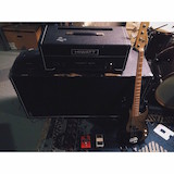
I have an amp splitter in a 1950a pedal enclosure and theres one input, 2 outputs. Before I had an amp selector I used it to run two amps... could this work to hook up the DR201 to two four ohm cabs? I doubt it, just trying to think of things I have to use.
I have an amp splitter in a 1950a pedal enclosure and theres one input, 2 outputs. Before I had an amp selector I used it to run two amps... could this work to hook up the DR201 to two four ohm cabs? I doubt it, just trying to think of things I have to use.